What it shows
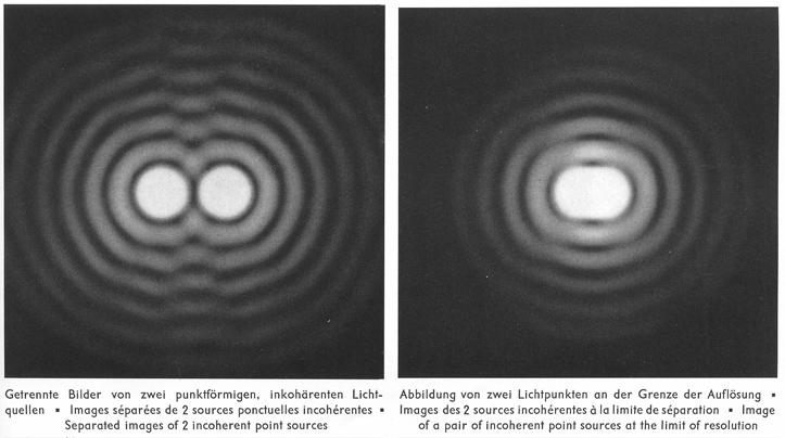
A telescope (with video output) at the front of the lecture hall is focused on two point light sources at the rear of the hall. Although the light sources are only 1/2 mm apart, they are readily resolved. The Rayleigh limit of resolution can be clearly shown by reducing the telescope aperture to the point where the two light sources can barely be resolved, similar to the following images (from: Cagnet/Francon/Thrierr, Atlas of Optical Phenomena). At the Rayleigh limit the centers of both point sources coincide with the the first minimum of the other source. Note that, since we are using white light sources and not a laser, one does not see as many interference maxima and minima in the Airy disk as pictured (see comment below for explanation).
The aperture can be further reduced past the Rayleigh limit so that it's impossible to resolve the two sources. Thus, a 1-inch diameter "spy glass" (or small binoculars) will not resolve the two point light sources, regardless how "powerful" the magnification or the quality of the optics.
How it works
The telescope1 is a Newtonian, utilizing a 4-inch (10 cm) concave primary mirror and a flat diagonal secondary mirror. It sits on an equatorial mount and dedicated tripod. Instead of an eyepiece, a CCTV camera2 is used for video projection of the image.
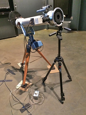
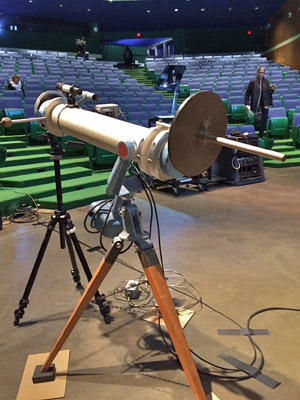
An adjustable iris diaphragm,3 mounted on its own tripod in front of the telescope, allows one to reduce the telescope aperture to any desired opening down 6 mm. The set-up is shown in the two photographs:
The two point light sources are located 20 meters away at the very back of the lecture hall. They are fashioned from two pin pricks in aluminum foil. The pinholes measure 0.14 +/- .04 mm in diameter and their separation is 0.45 mm, center-to-center. The aluminum foil is held by a 35 mm slide mount and a Kodak Ektagraphic slide projector provides the light. No lens is used in the slide projector—the telescope is focused directly on the two pinholes. The salient parameters are illustrated below:
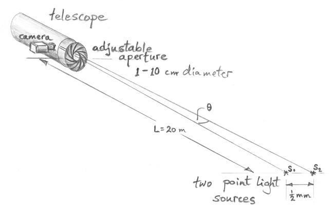
The angular separation of the two light sources is 2.5x10⁻⁵ radians. Setting this angular separation equal to the Rayleigh angular resolution limit, \(\theta = 1.22 {\lambda \over a}\) (where a is the aperture of the telescope), allows one to calculate the smallest aperture at which the light sources can still be resolved. Using 550 nm for the wavelength, one obtains 2.7 cm for the aperture. The experiment quantitatively confirms this result.
Setting it up
Since the overall magnification of the system is large, the image is quite succeptible to vibrations of the telescope. To minimize the problem, the legs of the tripod sit on squares of 1"-thick Sorbothane (see photograph above). Thin pieces of cardboard under the Sorbothane lessens the friction with the floor so that the tripod can be nudged for alignment.
The slide projector sits on a tall DA-LITE project-o-stand positioned against the back wall at the rear of the lecture hall. Since it is difficult to both aim and focus the telescope on the pinhole light sources, it's easier to first perform the focusing task. To that end, set a light box on the stand and tape translucent graph paper on it. Position the light box such that the graph paper is at the same location that the pinhole slide will be when the projector is in place. Now it's easy to aim the telescope at the light box and focus on the illuminated grid pattern of the graph paper. Having done that, replace the light box with the slide projector.
It is important to properly align the slide projector so that the telescope looks "squarely" at the slide. The following technique works well. Put a long focal length lens (use the 9" f/2.8 2x2 lens) in the projector and aim and focus the two pinholes on a white card positioned close to the telescope. A piece of 2x4 under the rear of the projector usually provides the right amount of tilt. Once aligned, remove the lens.
In performing the demonstration, it is necessary for the demonstrator to not only be able to turn the slide projector on and off from the front of the lecture hall but also, more importantly, adjust the intensity of the pinhole light sources. As the aperture of the telescope is made smaller, less light enters and the image becomes dimmer. To maintain the overall image brightness, the intensity of the projector lamp must be increased accordingly. To that end, we use a remote triac lamp control4 with a long cord that reaches from the front to the back of the lecture hall. The plug at the other end inserts into the 2-hole lamp control receptacle at the rear of the slide projector (to the right of the 5-hole slide remote control receptacle). The projector switch should be in the FAN ONLY position.5
The experiment requires a significant amount of time to set up. If only 1/2 hour is available before class, arrangements should be made to have as much of the apparatus set in place and ready. You can then devote your limited time for final adjustments.
Comments and notes
Only the first order minimum and maximum will be distinctly visible. This is because we have a superposition of interference patterns (Airy disk pattern) from a continuum of wavelengths across the visible spectrum. All these patterns have the same central maximum, but the pattern is more spread out for the longer wavelengths; this smears out the higher-order maxima and minima. For example, the second position where one obtains destructive interference for red light very closely coincides with the second maximum (constructive interference) for blue light. Furthermore, the limited dynamic range of light intensities reproduced by the video camera/projector makes it very difficult to capture the higher orders without completely saturating the central maximum.
1. Celestar 4 by Fecker
2. Panasonic Model WV-BP330 with a 1.25 Orion Combined Camera Adaptor (T-ring to C adaptor)
3. Rolyn Optics #75.0285 maximum aperture = 120 mm, minimum = 6 mm ($272 in 1999)
4. 600 W rotary dimmer (Grainger #4LX92)
5. If the two pins (that fit into the receptacle) are shorted together or connected by means of a switch, the lamp circuit will go to HIGH when the projector switch is in the FAN position. Note that the power is from the internal circuit of the projector ... do not connect the pins to an external power source!